Article
citation information:
Gherman, L., Chioseaua, B., Ghiciuc,
R. New
design of an electromagnetic launch system for tactical UAVs. Scientific Journal of Silesian University of
Technology. Series Transport. 2020, 108,
45-51. ISSN: 0209-3324. DOI: https://doi.org/10.20858/sjsutst.2020.108.5.
Laurian GHERMAN[1],
Bogdan CHIOSEAUA[2],
Raluca GHICIUC[3]
NEW
DESIGN OF AN ELECTROMAGNETIC LAUNCH SYSTEM FOR TACTICAL UAVS
Summary. UAVs in recent times have achieved an increased rate
of development, and hence, can cover a large spectrum of missions. Based on the
dimensions, we can find UAVs from large dimensions used to operate at the
global level through mini UAVs used inside buildings. The large UAVs are
operated almost like a manned aircraft. For this reason, it uses the airport
infrastructure and a runway for take-off and landing. The mini UAVs can be
launched by hand. Between these two extremes, there is a category of UAVs used
at the tactical level, which cannot be launched by hand and is not possible to
build a runaway. These UAVs are launched using RATO (rocket-assisted take-off)
or catapults. To improve the launch system, this should have a few moving parts
to reduce maintenance costs and be powered by electric energy to be easily
integrated into the automatic control loop. This paper presents a new design of
a launch catapult based on electromagnetic energy for tactical UAVs. This
technology is under development to launch projectiles with high velocity;
however, it has theoretically proved the possibility to equally launch UAVs.
The second part presents the theoretical approach necessary to find the
expression of force under certain approximation for electromagnetic launch
system design.
Keywords: UAV, Lorentz force, electromagnetic launch
system
1. INTRODUCTION
UAVs in recent times have achieved
an increased rate of development, and hence, can cover a large spectrum of
missions. Based on the dimensions, we can find UAVs from large dimensions used
to operate at the global level through mini UAVs used inside buildings. The
large UAVs are operated almost like a manned aircraft. For this reason, it uses
the airport infrastructure and a runway for take-off and landing. The mini UAVs
can be launched by hand. Between these two extremes, there is a category of UAVs
used at tactical level which cannot be launched by hand and is not possible to
build a runaway [1,3]. These UAVs are launched using RATO (rocket-assisted
take-off) or catapults. These installations are good solutions because:
-
the UAVs can be
launched without any infrastructure;
-
the payload weight
or the mission time can be increased as no fuel is used for launching;
-
this approach is
environmentally friendly.
The catapult installations use
different kinds of energy to accelerate the UAVs, these are:
-
mechanical energy
stored in springs or rubber bungee;
-
pneumatic/hydraulic
energy produced by cylinders and pistons;
-
electromechanical
energy produced by electrical motors.
To improve the launch system, this
should have few moving parts to reduce maintenance costs and be powered by
electric energy as well to be easily integrated into the automatic control
loop. This paper presents a new design
of a launch catapult based on electromagnetic energy for tactical UAVs. This
technology is under development to launch projectiles with high velocity; however,
it has theoretically proved the possibility to launch UAVs too.
In this paper, we present the theoretical results obtained during a project aimed to explore new ways to accelerate a mass using electromagnetic energy. The objective of the project is to accelerate a projectile with a mass of 200 kg from zero to 25 m/s using 5 metres of acceleration length. According to this objective, the kinetic energy of the mass is:
![]() (1)
(1)
If we assume the initial speed is zero and the acceleration force acting on the projectile is constant, then the value of the force is:
![]() (2)
(2)
![]() (3)
(3)
According to our project objectives, the accelerating force acting on the projectile is Lorentz force. The equation of Lorentz force based on current intensities sometimes presented as Laplace force is:
![]() (4)
(4)
![]() (5)
(5)
where
α is the angle between vectors ![]() and
and![]() .
.
We created a design where the magnetic field is perpendicular on the current caring wire (α=900) [4,5,6,7].
2. NEW EMLS DESIGN
Our design consists of a static part,
which is made by a pair of coils similar to Fig. 1. The coils are square with
the outer length calculated at the dimension of 180 mm and the inner length
calculated at the dimension of 100 mm. The number of turns N depends on the size of the wire. We are looking for a copper wire
that is able to sustain a fussing current calculated per Onderdonk for 32 ms up
to 1000 amperes. From the table with the American wire gauges, we find AWG 19
with 0.912 mm diameter. At this dimension of wire, we can accommodate N =4000 turns in the rectangle cross-section
area obtained from calculations. Because only one pair of coils are not enough
to accelerate a tactical small UAV, we will use many pairs which form stages of
acceleration. For our simulation, we used 4 stages of acceleration. The length
of each stage is calculated at the dimension of 100 mm. This acceleration coils
provide the current intensity I and length l of the conductor
inside the magnetic field presented in Equation 5.
Because the number of conductors is
equal with the number of turns N, the Lorentz force will be multiplicate
with N. Each coil on stage produce an acceleration force so the total
net force on each stage is multiplied by 2.
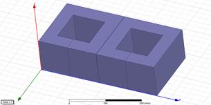
Fig. 1. Static coils for
acceleration path
In Fig. 2, we present the 2 coils
made to produce the magnetic field B required by the Lorentz force. These 2
coils are in front of the acceleration stator. The coils are square with the
outer length calculated at the dimension of 180 mm and the inner length
calculated at the dimension of 100 mm. The number of turns N is 1600. The length of the coils in axe x direction is 40 mm.
These two coils are the moving parts. The magnetic field produced by moving
coils and the intensity of the current in static coils create an acceleration force
in positive z direction.
To increase the efficiency of the
system, we also created a magnetic circuit made by electromagnetic steel. The
shape and position of this core is presented in Fig. 3.
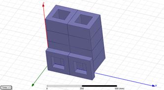
Fig. 2. Moving coils in front of
acceleration stages
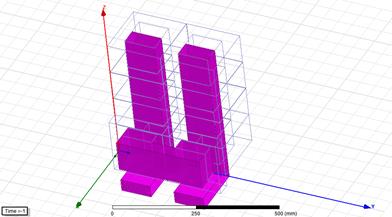
Fig. 3. The magnetic core
The entire design is presented in Fig.
4. The number of acceleration stages can be increased accordingly as needed.
For our simulations, we used only 4 stages. We used the same amount of current
to power all coils. Because we have moving coils, we can power these coils
using moving contacts. This approach is possible given the maximum current used
is 1000 A. The acceleration Lorentz force is:
![]() (6)
(6)
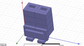
Fig. 4. New EMLS design
3. SIMULATIONS
For simulations, we chose the Maxwell interactive software package
that uses the finite element method (FEM) to analyse and solve 3D
electromagnetic field problems [2]. First, we built the simulation model with
the same dimensions as we used to calculate the theoretical values of current
intensity I, acceleration force F, and muzzle velocity v.
Because the acceleration length is 5 m and our simulations are for only 0.1 m
the value of velocity, we expect from the simulation is 0.5 m/s.
![]() (7)
(7)
![]() (8)
(8)
According to theoretical calculus,
we need a force of 250 N to accelerate a mass of 200 kg from 0 m/s to 0.5 m/s
on a length of 0.1 m. This length is the length of an acceleration stage. From the
simulation, we obtained that the necessary value of current intensity to
achieve a speed of 0.5 m/s is 4 amperes.
Fig. 5. Variation of acceleration
force in time
In Fig. 5 is displayed with a
continuous line, the variation of acceleration Lorentz force in time. As expected,
the force is not constant as in our theoretical calculus. With dots is
displayed the position of mobile coils in time. Based on this acceleration
force, the velocity of mobile coils after the first stage is 0.5 m/s in
accordance with our goals.
Therein Fig. 6 is displayed with
continuous line, the variation of speed in time. At the end of first stage
after 0.1 m the velocities of mobile coils achieve the value of 0.5 m/s. With
dots is displayed the position of mobile coils in time.
According to the results from
this simulation, we can predict that the system is able to accelerate a mass of
200 kg from 0 to 25 m/s on 5m length of acceleration using only 4 amperes
current.
Fig. 6. Variation of speed in time
3. CONCLUSION
In this paper, we proved theoretically though the simulation, the possibility to obtain desired muzzle velocities of a tactical UAV using a current with low intensity of 4 A.
If the acceleration mass is increased, the intensity of the current should be increased to obtain the desired muzzle velocity.
Fig. 7. Variation of acceleration force in time for I=1000A
The great advantage of this design is the adaptability to different applications. If we need to increase the acceleration force, we can increase the current up to 1000 A and increase the number of systems up to 4 as well. According to simulations results, this design can be easily used to accelerate projectiles up to 3000 m/s. This system can be an electromagnetic catapult or a coilgun.
To prove this affirmation, we displayed in Fig.
7 with a continuous line, the
variation of acceleration Lorentz force in time for I=1000A and the
mass of 1 kg.
Acknowledgements
The paper was prepared under the project
“Micro launcher based on detonation engine – MILADEE”,
Contract 174/2017 with Romanian Space Agency, STAR Program.
References
1.
Kozuba
J., T. Muszyński. 2010. “Computational
fluid dynamics methods used in unmanned aerial vehicle design”. Proceedings
of the 4th World Congress Aviation in the XXI century - Safety in
aviation and space technology 1: 15.56-15.59. September 21-23, Kijow 2010.
2.
Kozuba
J., A. Bondaruk. 2014. “Flight simulator as an essential device
supporting the process of shaping pilots situational awareness”. Proceeding
at International Conference of Scientific Paper – AFASES 2014: 695-714. Brasov 22-24 May 2014.
ISSN-L 2247-3173.
3.
Moşoiu O., I. Bălăceanu, M. Moldovan. 2017. “New
operational requirements of the integrated defense system in the hybrid war
conditions”. Review of the Air Force Academy 1(33).
4.
Balikci A.,
Z. Zabar, L. Birenbaum, D. Czarkowski. 2007. “On
the design of coilguns for super-velocity launchers”. IEEE Trans. on Magnetics 43(1): 107-110.
5.
Kurt A. Polzin, Jake E. Adwar, Ashley K. Hallock.
2013. “Optimization of Electrodynamic Energy
Transfer in Coilguns with Multiple, Uncoupled Stages”. IEEE Trans. on Magnetics 49(4): 1453-1460.
6.
Wenbo L., W. Yu, G. Zhixing, Y. Zhongming, C. Weirong. 2013.
“Connection pattern research and experimental realization of single stage
multipole field electromagnetic launcher”. IEEE Trans. on Plasma Science 41(11): 3173-3179.
7.
Abdalla M.A., H.M. Mohamed.
2016. „Asymmetric multistage synchronous inductive coilgun for length
reduction, higher muzzle velocity, and launching time reduction”. IEEE
Transactions on Plasma Science 44(5): 785-789. DOI:
10.1109/TPS.2016.2543500.
Received 27.03.2020; accepted in revised form 19.06.2020
![]()
Scientific
Journal of Silesian University of Technology. Series Transport is licensed
under a Creative Commons Attribution 4.0 International License